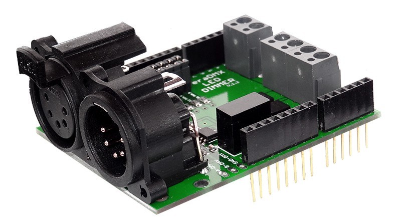
TeraDMX is fully isolated DMX LED DIMMER Shield for Arduino is designed to connect your project to professional large size DMX networks. It can control high-current (9-24V lamps, relays, solenoids, motors, etc.) or low-current TTL (for servos and small LEDs) output. This shield has been designed to restrain EMI and to eliminate ground loops specifically. Ideal for DMX projects without risking processor damages from high voltage peaks.
The shield is based on a ST485EBDR which has very good ESD protection properties, it allows you to connect up to 256 devices on a single bus!
All components have been carefully selected on their characteristics to ensure proper isolation and performance.
The following settings are configurable via the onboard jumpers:
- Receive data via RX or other pin via wire jumper
- PWM ch1 via 9 PIN or other pin via wire jumper
- PWM ch2 via 10 PIN or other pin via wire jumper
- PWM ch3 via 11 PIN or other pin via wire jumper
- Terminator 120 Ohm
The shield comes standard in a 5 pin XLR version, 3 pin versions is available as well. PCB is design to fit both of them.
Every board is tested before shipping to provide high quality service.
This DMX Shield is a high quality solution for reasonable costs that allows you to connect your Arduino driven artwork safely into DMX512 networks.
Features
- Open-source (Schematics, PCB layout, GERBER files and source code ale available for everyone for free)
- 3 x 6A PWM LED outputs
- 9-24V input
- PCB designed for 3 or 5 XLR PIN sockets
- Terminator 120 Ohm selected by jumper
- Crossable control pins
- ESD protection (ST485EBDR transceiver)
± 15 kV (HBM)
± 8 kV (IEC-1000-4-2 contact discharge) - Opto isolation (6N137SDM Transoptor)
Superior CMR – 10 kV/us- Galvanic decoupling (DC/DC Converter)
Input / Output isolation 1000 VDC
- Galvanic decoupling (DC/DC Converter)
- LED Data indicator
Isolation
For a simple setup it is possible to connect the Driver chip directly to the Arduino pins but if you need a robust system, especially on a stage environment, you will have to add some more electronics to avoid electrical damage by defect equipment or accidental circumstances.
The electric potential of the DMX side of the implementation have to be isolated from the processor. There are 2 sort of chips that implement all you need:
- A 5 volt to 5 volt DC/DC converter with galvanic decoupling. There are complete solutions in a single component available like AM1S-0505SZ that can be used to generate a 5V power supply that is galvanic isolated up to 1000V. So even if there is a high voltage attached to the DMX bus there is a chance of no or low damage.
- High speed TTL compatible Optocoupler These chips use a LED and light sensitive transistor to isolate the DMX bus from the Arduino data pins. There are standard TTL compatible Optocouplers available like the 6N137.
Arduino Software
(https://github.com/maniakm/TeraDMX)
The Conceptinectics DMX Library for Arduino can be downloaded from the source forge website. https://sourceforge.net/projects/dmxlibraryforar/files/
Sample code for this shield is provided below.
In case you have the shield configured to use the RX pin you have to disable the shield before you can upload your new sketch onto the Arduino board. This jumper allows you to disable the shield without disconnecting it from the Arduino board which saves time.
#include <Conceptinetics.h>

#define DMX_SLAVE_ADDRESS    1 //DMX address
#define DMX_SLAVE_CHANNELS   4 //DMX channels

// Configure a DMX slave controller
DMX_Slave dmx_slave ( DMX_SLAVE_CHANNELS );

//PIN configuration
const int StatusLed = 13;
const int PWM_R = 11;
const int PWM_G = 10;
const int PWM_B = 9;

unsigned long       lastFrameReceivedTime;
const unsigned long dmxTimeoutMillis = 10000UL;

// the setup routine runs once when you press reset:
void setup() {

  // Enable DMX slave interface and start recording
  // DMX data
  dmx_slave.enable ();

  // Set start address to 1, this is also the default setting
  // You can change this address at any time during the program
  dmx_slave.setStartAddress (DMX_SLAVE_ADDRESS);

  //
  // Register on frame complete event to determine signal timeout
  //
  dmx_slave.onReceiveComplete ( OnFrameReceiveComplete );

  // Set led pin as output pin
  pinMode ( PWM_R, OUTPUT );
  pinMode ( PWM_G, OUTPUT );
  pinMode ( PWM_B, OUTPUT );
  pinMode ( StatusLed, OUTPUT );
}

// the loop routine runs over and over again forever:
void loop()
{

  float M = dmx_slave.getChannelValue (1) / 255.0f;
  int R = dmx_slave.getChannelValue (2) * M;
  int G = dmx_slave.getChannelValue (3) * M;
  int B = dmx_slave.getChannelValue (4) * M;

  analogWrite(PWM_R,R);
  analogWrite(PWM_G,G);
  analogWrite(PWM_B,B);

  if(millis() - lastFrameReceivedTime > 3000)
  {
    digitalWrite(StatusLed,HIGH);
    analogWrite(PWM_R,255);
    analogWrite(PWM_G,0);
    analogWrite(PWM_B,0);
  }
}

bool sta = false;
void OnFrameReceiveComplete (unsigned short channelsReceived)
{
  if ( channelsReceived == DMX_SLAVE_CHANNELS)
  {
    // All slave channels have been received
    //digitalWrite(StatusLed,LOW);
  }
  else
  {
    // We have received a frame but not all channels we where
    // waiting for, master might have transmitted less
    // channels
  }

  digitalWrite(StatusLed,sta);
  sta = !sta;
  // Update receive time to determine signal timeout
  lastFrameReceivedTime = millis ();
}
PC Software
You can use PC with DMX controller via USB (Enttec Open DMX) and special software (Q Light Controller).
We provide configuration file for Q Light Controller as well.

How it’s made
Shield is designed and produced by me. Here you can see soldering process.